Description

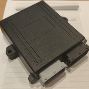
 The CMC MAX is a device from the value-line.
It communicates with slave modules and or batteries equipped with onboard CMC’s. Depending on its firmware it will can help you with communication and or become a BMS.
The data is populated on the CanBus (BGTW Firmware)
- Cell data;
- Balancing commands;
- Temperatures;
By installing the BMS firmware this device becomes a BMS** with the following functions:
- Contactor control;
- Charge/Discharge rate;
- Temperature monitoring;
- Balance monitoring & control;
- Charger control*;
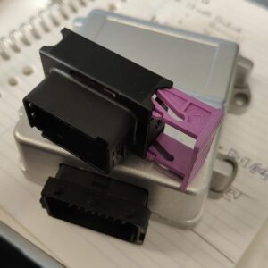
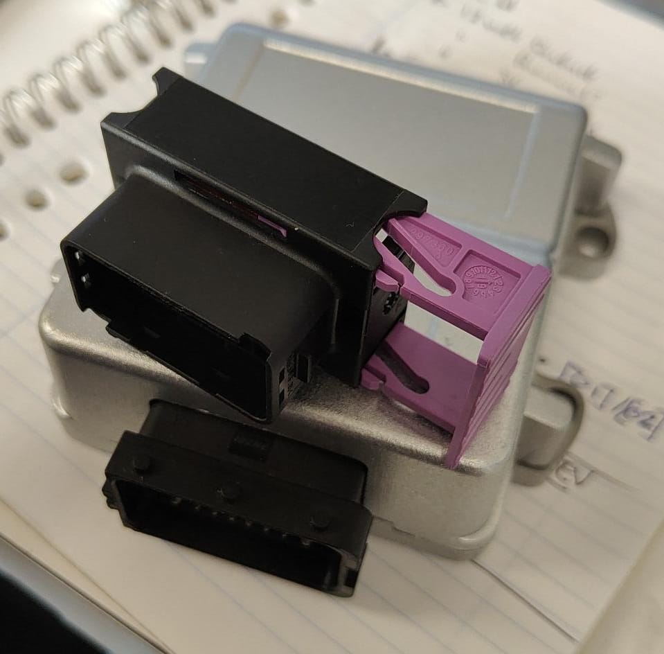
The device could carry*:
- 1 TX/RX port;
- 2 CanBus interfaces;
- Digital Inputs;
- Digital outputs (current sinking);
- Further IO depends on config:
- Analog Inputs;
- PWM outputs (push/pull) low power (optional);
- LIN BUS (optional);
- RS-232 (optional);
- RS-485 (optional);
- max. 30kw inverter support;
the IO’s are CanBus readable/writable.
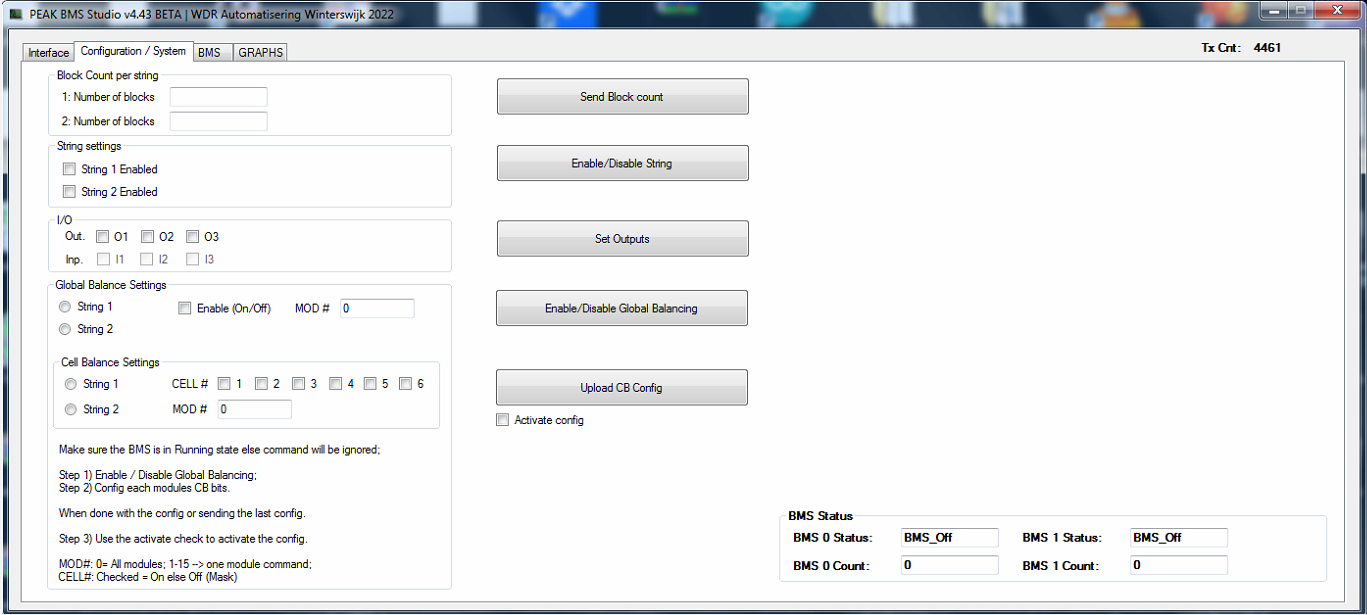
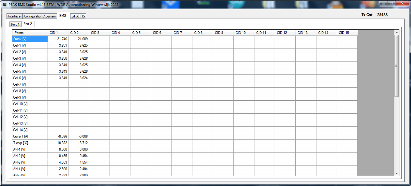
The product comes with a PEAK CAN or BUSMUST Interface Compatible software suite. Consisting of a firmware updater (over CanBus) and a BMS Studio.
The studio permits to test/verify/monitor the installation.
Firmware choices**:
- BGTW = bare metal CANBus data and commands;
- For OEM integrators;
- BlueBMS = basic BMS Firmware;
- If you don’t need Hybrid Storage inverter communications;
- ESSBMS = BMS Firmware dedicated to support communications with Hybrid Storage inverters (current list);
Customer changes and or wishes can be discussed :).
* Because of current market conditions configurations of the device may vary; discuss your needs upfront with us.
** This product is continuously improved; expect regular updates which increase functionality.